In order to leverage the capabilities of the EBAZ4205 I want it to run Linux. There are a couple of guides online which didn't work for me, because I have the board variant without a Y3 crystal at the ethernet IC. I'm also not an experienced FPGA developer, so some of the implicit steps were non-trivial for me at all. This was an excellent opportunity to pick up the glove and learn how to build Petalinux myself. So lets get to work!
This guide uses 2019.1 toolchain, for two main reasons:
- It is the last version before Xilinx's migration to Vitis so there is more data online from other users.
- While the hardware flow is identical to the Vivado 2020.X editions, the Petalinux u-boot build process is different (see Tux Engineering, Inc. - Home), and has resulted errors for me, which I currently don't know how to solve.
Refences
The full writeup puts together bits and pieces are from the following sources:
[1] zynq[1] 矿板helloworld | hhuysqt (using Google-Translate)
[3] EBAZ4205 IP101GA no Y3 crystal | 0xFE (cystal-less board)
Pre-Requisites
- An EBAZ4205 board with power supply and a serial to USB converter
- A PC with 200GB-300GB hard drive available.
Build steps
1. Software installation:
There is a fantastic walkthrough here: How to Install PetaLinux 2019.1 - FPGA Developer. I chose to install it on Ubuntu 18.04.2 since it was suggested in other websites that it might be safer.
The only issue that I encountered was that Xilinx is trying to install to a root directory. You can solve this in one of two ways:
a. Install Vivado with sudo.
sudo ./xsetup
b. Before vivado installation create /tools/Xilinx yourself and give your user write/execute permissions.
sudo mkdir /tools/Xilinx
sudo chown <user-name> /tools/Xilinx
sudo chmod u+rwX /tools/Xilinx
2. Build base hardware description:
Start Vivado. If you don't have a vivado desktop shortcut created.
source <vivado installation dir.>/Vivado/2019.1/settings64.sh
vivado &
Quick Start -> Create Project. Next -> set a location -> Next.

RTL Project, No sources at this time -> Next.

Select the EBAZ4205 chip (xc7z010clg400-1) -> Next.

Verify, finish.

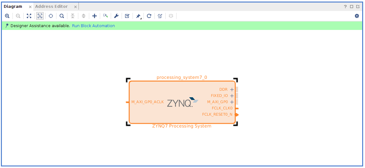
In Vivado add the processor block-IP cells. IP Integrator -> Create block design-> name it -> OK.

Add a Zynq Processing System.

Double click the block to edit the Zynq ports.
Add NAND flash.

Add IOs: Ethernet, SD0, UART1 (note the pins!)

Configure Ethernet clocks (Note the 100Mb/s change).

Add a 25MHz clock. This is required for ethernet without external crystal.

Petalinux requires a TTC timer to be defined for the PS (processor IP) to use.

Add DDR: there is a similar part ending with HA-15E. I don’t know what’s the difference but datasheet says that I have the 125.

You now can see the additions that were made to the processor block. Click OK.

Apparently, the GMII (1Gb/s) module is 8 bit TX/RX and MII (100Mb/s) is 4 bit, so some concatenation is needed. I don’t know if the following is required, but this works: add two "concat" modules for both RX and TX, same way you added the processing unit.

double click to edit number of bits and IOs. The RX is 2-inputs x 4bit each, the TX is 1 input x 4bit.

Click + next to GMII_ETHERNET0 to expand, connect blocks to concat, and FCLK_CLK0 -> M_AXI_GPO_ACLK by click and drag line.
 Point at a port. Right-click. Choose “Make
External” to create a port for ENET0_GMII_TX_EN.
Point at a port. Right-click. Choose “Make
External” to create a port for ENET0_GMII_TX_EN.
Make external the following ports.

Click “-“ next to GMII_ETHERNET_0 to make compact. Double click on a port, e.g. “dout_0[3:0]” and rename to reflect its function. Click “enter” to apply. Repeat for all the ones marked (This is not strictly necessary, but you'll need to use your own names in the constraint files below if you don't keep my naming).

Go to sources, right-click design -> Creat HDL Wrapper-> Let Vivado manage... -> OK.

A warning pops, essentially telling us that the upper bits of ENET0_GMII_TXD are unconnected (what we want anyways). Click OK to authorize.
Create a constraint file. Right-click Constrains-> Add sources.

Add or create constraints -> Next.

Create File -> <Your file name> -> OK -> Finish.

Double click the generated file.
Copy-paste the constraints from below. There are 15 pin assignments and 15 I/O type definitions.
set_property IOSTANDARD LVCMOS33 [get_ports ENET0_GMII_RX_CLK_0]
set_property IOSTANDARD LVCMOS33 [get_ports ENET0_GMII_TX_CLK_0]
set_property IOSTANDARD LVCMOS33 [get_ports FCLK_CLK1]
set_property IOSTANDARD LVCMOS33 [get_ports {enet0_gmii_rxd[3]}]
set_property IOSTANDARD LVCMOS33 [get_ports {enet0_gmii_rxd[2]}]
set_property IOSTANDARD LVCMOS33 [get_ports {enet0_gmii_rxd[1]}]
set_property IOSTANDARD LVCMOS33 [get_ports {enet0_gmii_rxd[0]}]
set_property IOSTANDARD LVCMOS33 [get_ports {ENET0_GMII_TX_EN_0[0]}]
set_property IOSTANDARD LVCMOS33 [get_ports {enet0_gmii_txd[3]}]
set_property IOSTANDARD LVCMOS33 [get_ports {enet0_gmii_txd[2]}]
set_property IOSTANDARD LVCMOS33 [get_ports {enet0_gmii_txd[1]}]
set_property IOSTANDARD LVCMOS33 [get_ports {enet0_gmii_txd[0]}]
set_property IOSTANDARD LVCMOS33 [get_ports ENET0_GMII_RX_DV_0]
set_property IOSTANDARD LVCMOS33 [get_ports MDIO_ETHERNET_0_0_mdc]
set_property IOSTANDARD LVCMOS33 [get_ports MDIO_ETHERNET_0_0_mdio_io]
set_property PACKAGE_PIN U14 [get_ports ENET0_GMII_RX_CLK_0]
set_property PACKAGE_PIN U15 [get_ports ENET0_GMII_TX_CLK_0]
set_property PACKAGE_PIN U18 [get_ports FCLK_CLK1]
set_property PACKAGE_PIN Y17 [get_ports {enet0_gmii_rxd[3]}]
set_property PACKAGE_PIN V17 [get_ports {enet0_gmii_rxd[2]}]
set_property PACKAGE_PIN V16 [get_ports {enet0_gmii_rxd[1]}]
set_property PACKAGE_PIN Y16 [get_ports {enet0_gmii_rxd[0]}]
set_property PACKAGE_PIN W19 [get_ports {ENET0_GMII_TX_EN_0[0]}]
set_property PACKAGE_PIN Y19 [get_ports {enet0_gmii_txd[3]}]
set_property PACKAGE_PIN V18 [get_ports {enet0_gmii_txd[2]}]
set_property PACKAGE_PIN Y18 [get_ports {enet0_gmii_txd[1]}]
set_property PACKAGE_PIN W18 [get_ports {enet0_gmii_txd[0]}]
set_property PACKAGE_PIN W15 [get_ports MDIO_ETHERNET_0_0_mdc]
set_property PACKAGE_PIN Y14 [get_ports MDIO_ETHERNET_0_0_mdio_io]
set_property PACKAGE_PIN W16 [get_ports ENET0_GMII_RX_DV_0]

Save, generate bitstream. This will run synthesis and implementation as well. Make sure to use all your cores if you value your time. The same "concat" warning will pop again. Authorize it.
 When done, choose Open Implemented Design -> OK (This is not really important but done for good order).
Click File -> Export -> Export Hardware.

Make sure you check-in the "Include Bitsream" box.

And that's it for the hardware part!
3. Build Petalinux.
Start a terminal. Go to your Petalinux installation directory, make a project directory, step into it.
cd ~/petalinux/2019.1/
mkdir projects
cd projects
Invoke petalinux, make a new project, step into its library.
source ~/petalinux/2019.1/settings.sh
petalinux-create --type project --template zynq --name EBAZ4205_Petalinux_2019_1
cd EBAZ4205_Petalinux_2019_1/
Start the petalinux configuration process. For this you need your to point to the library where your .hdf fileis. It's in your vivado project directory. In my case it's at:
petalinux-config --get-hw-description=~/Vivado/2019.1/EBAZ4205_Petalinux_Base/EBAZ4205_Petalinux_Base.sdk
The config window should pop up. Navigate your way through it. The changes that I found that needed to be done are highlighted. Personally for me, compared to the default only the u-boot partition needs to be changed to "primary sd", and the netboot offset to be changed to 0x08000000 (I'm not sure if or why this is necessary, but it works). YMMV.

If you click exit from the top menu, the config process starts running.

Build Petalinux. This took me ~20 minutes.
petalinux-build
Apparently, if you rebuild you need to use (I personally prefer to just wipe the project and restart but YMMV):
petalinux-build -x mrproper -f

Package the project. For this you need your vivado bitstream which is in a cumbersome location like <Vivado Project Name>/<Vivado Project Name>.runs/impl_1/<hdl_wrapper_name>.bit. In my case:
petalinux-package --boot --format BIN --fsbl ./images/linux/zynq_fsbl.elf --fpga ~/Vivado/2019.1/EBAZ4205_Petalinux_Base/EBAZ4205_Petalinux_Base.runs/impl_1/Zync_proc_wrapper.bit --u-boot --force
From your Petalinux <project library>/images, copy BOOT.bin and image.ub to a micro-SD formatted in FAT32.
Set your EBAZ4205 jumper resistor to boot from SD, connect the serial adapter, open a terminal, and connect power.
If all went well you can log in to root (password: root), and ping 8.8.8.8 with a reply:
ping 8.8.8.8
Another good test is to query NIST website for the date and time:
cat </dev/tcp/time.nist.gov/13
And here you go. Your own fresh Linux installation running on a Zynq SoC board!
Thank you for this post! I had difficulty following others that did not show all steps.
ReplyDeleteThe first time I tried my boot.bin was only ~680KB, and did not boot. After double checking everything in vivado, regenerating the xsa file, and doing the petalinux part from scratch, it was about ~2.8MB and works now.
One change I did was to use EMIO for UART1, since I have the expansion board with a CH340 USB UART adapter. This involved making the UART external and setting J18 as RX and G20 as TX in the xdc file, which are mapped to the Data2 header.
Also, since my board does have the Y3 crystal for ethernet, I skipped making the extra clock signal.
If anyone reads this and is having trouble getting Linux working, I would recommend using the hardware platform in Vitis to try 1) the baremetal hello world, to test your serial port is working and 2) the baremetal lwip TCP iperf server, to test your ethernet is working. If those are working, then the issue is probably in the Linux build stage.
For enet0_gmii_txd, you might want to use the "Slice" IP instead of the xlconcat_0, this allows you to chop down the 8-bit output to 4-bit without warnings, and also provide a 4-bit "Constant" 4'b0 input for the high 4-bits of xlconcat_1, again this gets rid of another pesky warning.
ReplyDelete